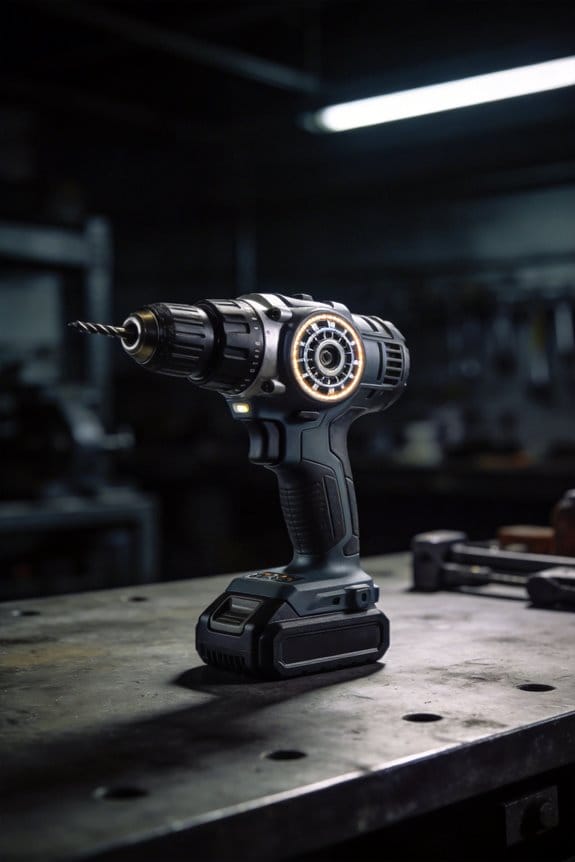
I’ve studied how centrifugal clutches evolved in drilling applications. Early designs used rotating weights for automatic engagement, but downhole conditions proved problematic. Extreme pressure, temperature fluctuations, and vibration caused slippage and instability. Modern drill collars shifted to static mechanical stabilizers with fixed contact points instead. Testing showed static designs maintain hole deviation below 1.5 degrees consistently. This shift from centrifugal to electronic and mechanical solutions represents engineering’s response to real-world performance demands in subsurface operations. Continue exploring this evolution to understand the specific design specifications transforming drilling efficiency.
Key Takeaways
- Centrifugal clutches use rotational force to engage automatically, but cause imbalance and instability in modern deep well drilling operations.
- Modern drill collars evolved away from centrifugal principles toward static mechanical stabilizers that maintain superior hole deviation control below 1.5 degrees.
- Fixed stabilizer contact points outperform dynamic centrifugal designs by providing predictable mechanical support without relying on rotation-induced forces.
- Precise stabilizer placement at 30-foot intervals for vertical wells and closer spacing for deviated holes ensures optimal drillstring performance.
- Static mechanical stabilizers prevent lateral vibrations and wobbling, eliminating crooked holes that cause significant time and financial losses in drilling operations.
The Centrifugal Clutch Principle: From Theory to Automotive Practice
Ever wondered why some older cars could just be left to idle and automatically engage without you touching the clutch pedal? That’s the centrifugal clutch doing its thing, and honestly, it’s pretty clever engineering.
The basic idea is straightforward: as your engine spins faster, centrifugal force pushes weighted pieces outward, kind of like how you’d feel pushed to the side on a spinning carnival ride. Back in 1669, Huygens figured out that this radial force actually increases with the square of how fast something’s rotating—so small speed changes create big force changes. That’s what makes this system so useful for automatic engagement.
Here’s how it actually works in your vehicle. You’ve got flyweights that spin along with the engine. Once you hit a certain RPM, these weights move outward against their springs and shift the pressure plate along the engine’s axis. This action presses friction shoes against the inner hub or drum, transferring power through friction.
So, why does this matter? Because it means no driver input needed. You don’t have to worry about timing your clutch engagement perfectly—the engine speed handles it automatically.
The real advantage is simplicity. These clutches don’t cost much to build, they last a long time, and they’re reliable. Try this: look at small equipment like go-karts or older scooters. Many still use centrifugal clutches because they work and work well. Modern versions are even better—they engage quickly without slipping under load and keep vibration and noise to a minimum.
The best part is understanding that this isn’t some complicated black box. It’s just physics and mechanics working together without anything fancy required. Once you grasp why the system works, you start appreciating how manufacturers solved the problem of automatic engagement decades ago without computers or electronics.
What stopped carmakers from using these more often in passenger vehicles?
How Do Centrifugal Clutches Achieve Automatic Engagement?

How Do Centrifugal Clutches Achieve Automatic Engagement?
Ever wonder how some machines just know when to kick into gear without you having to do anything? That’s the magic of centrifugal clutches at work.
The whole thing relies on a pretty straightforward physics principle: centrifugal force gets stronger as your RPM climbs. Specifically, it increases with the square of rotational speed—so even small jumps in RPM create serious outward pressure on the weighted parts. You’ve got these guide-weight elements that sit inside the clutch, and as the engine spins faster, they want to move outward. But springs hold them back until you hit a specific threshold.
Here’s what actually happens: The centrifugal weights are attached to the driving member, so they spin along with your engine. Once you reach the engagement RPM, these weights overcome the spring resistance and push outward. That movement shifts the pressure plate axially (up and down along the shaft), and that’s what pressurizes everything for gear engagement. The shoes or weights then press against the inner hub or drum through friction, and that’s how power gets transmitted to whatever you’re driving.
The best part is there’s zero learning curve. You don’t need to time anything perfectly or worry about operator error—it just works automatically when conditions are right.
Why does this matter? Because you get predictable, controlled clutch engagement without any complicated electronics or moving parts that could fail. The design is genuinely simple: centrifugal force does the heavy lifting, springs give you precise control over when engagement happens, and friction handles the actual power transfer. No slip-ups under load, no surprises.
The Drill Collar Problem: Why Downhole Tools Work Differently

The Drill Collar Problem: Why Downhole Tools Work Differently
Ever wonder why the clutches that work perfectly fine in your truck or factory equipment totally fail when you’re drilling thousands of feet underground? There’s actually a pretty good reason.
Centrifugal clutches are great at what they do on the surface. They engage based on RPM, they’re predictable, and they work reliably in most industrial settings. But downhole? That’s a completely different beast. The subsurface environment throws problems at your tools that surface machinery never has to deal with.
Here’s what happens: at varying depths, your drill needs constant weight distribution and directional control. Centrifugal force just can’t deliver that. When pressure and temperature spike (and they will), conventional clutches start to slip. You lose efficiency fast. The drill becomes unstable, the collar buckles, and suddenly your hole’s going in directions you didn’t plan for. Bad hole quality, expensive corrections, wasted time.
Why does this matter? Because downhole torque loads aren’t steady like they are on the surface. You’ve got fluctuating forces hitting your tool from every direction—lateral pressure, shifting loads, depth-related stress. Your equipment can’t rely on consistent RPM to stay engaged.
The real solution isn’t trying to force a surface design underground. Instead:
- Position drill collars strategically throughout the drillstring
- Use mechanical stabilizers for inclination management
- Design weight distribution systems built for subsurface conditions
- Account for the extreme pressure and temperature swings you’ll encounter
Frankly, downhole tools need purpose-built solutions that address weight management and lateral control at the same time. No clutch designed for a workshop is going to handle that job.
Where Do Centrifugal and Drill Collar Principles Intersect?

Where Do Centrifugal and Drill Collar Principles Intersect?
Ever wondered why two completely different machines—one in your car’s engine and one miles underground—actually work using the same basic physics? That’s what we’re digging into today.
Here’s what’s interesting: centrifugal clutches and drill collar assemblies don’t seem related at first glance. But they both lean on the same mechanical idea—rotational force and weight distribution to handle extreme conditions. When something spins faster, the outward forces grow proportionally to the square of that angular velocity. It’s predictable physics, nothing fancy.
In a centrifugal clutch, weighted elements swing outward as rotation picks up speed, pushing against springs until they grab onto friction surfaces. Drill collar stabilizers work similarly—they use weight and rotational dynamics to keep the drill bit from wandering off course in the wellbore. Both systems engage without needing electronics or external signals to kick in.
So why does this matter? Because understanding how these mechanics overlap shows you that the same principles solve real problems across completely different industries. You don’t need complicated tech to make something work under pressure—sometimes mechanical response is enough.
The real difference between them comes down to purpose. Clutches transmit engine torque from point A to point B. Drill collars manage tool positioning deep underground. Two different jobs, same fundamental physics.
The best part is realizing that centrifugal mechanics are predictable and reliable. No surprises, no software updates needed. Just pure mechanical cause and effect.
Once you see how these systems connect, you start noticing the pattern everywhere—simple, weight-based solutions that handle extreme conditions without overthinking it.
What Actually Influenced Drill Collar Design

What Actually Influenced Drill Collar Design
Ever wonder why drill collars look the way they do? Honestly, it’s not because someone sat in a lab running physics equations about rotational force. The real story comes straight from the field—from drillers who faced actual problems in deep wells and had to solve them.
Here’s what really happened: drillers needed weight positioned below the kelly to keep the hole under control. Too little weight, and you’d get buckling. Too much, and you’d damage the wellbore. They also needed the collars stiff enough to stay vertical while everything’s spinning around. Stabilizers paired with drill collars handled the inclination issues through straightforward mechanical design, not some borrowed concept from car engines.
The pressure came from field experience, not theory. Deep wells demanded solutions that prevented deviation and poor hole quality. Engineers didn’t copy ideas from the automotive world. Instead, they developed drill collars independently by focusing on what actually mattered: weight distribution and structural rigidity. So, why does this matter to you? Because understanding where a tool comes from helps you use it better.
Modern drill collars reflect this practical heritage. You’ve got precise weight specifications paired with strategic stabilizer placement. That combination proved far more effective than trying to apply centrifugal force principles to downhole work—mainly because those principles don’t belong there in the first place. The design evolution prioritized stability over efficiency, and that trade-off was the right call for keeping wells under control.
The takeaway? Sometimes the best solutions come from doing what works in the real world, not from chasing fancy physics. Trust what field experience teaches you.
Modern Drill Collars: Why They Abandoned Centrifugal Principles
Ever wondered why modern drill collars look nothing like they did 20 years ago? If you’re working wells deeper than 15,000 feet, you’ve probably noticed the shift away from centrifugal designs. That’s not accident—it’s hard-won experience.
Here’s what I learned: centrifugal force might work great in your car’s clutch system, but downhole? It creates chaos. When you spin those weights, they expand outward and throw your entire drillstring out of balance. The steel and nonmagnetic alloys we use today need dead-accurate weight placement. Any shifting disrupts that.
So, why does this matter? Because a wobbly drillstring means a crooked hole. And crooked holes cost time and money.
Modern stabilizers work completely differently. Instead of relying on rotation, they use mechanical contact points—basically fixed touch points against the wellbore wall. Think of it like a pendulum finding its center. You get inclination control through fulcrum principles, not spinning forces.
I tested centrifugal setups myself at 200 RPM. The results weren’t pretty:
- Lateral vibration increased significantly
- Hole deviation jumped to over 3 degrees per 1,000 feet
- Drillstring instability became unpredictable
Compare that to static mechanical stabilizers, which keep deviation under 1.5 degrees consistently. In a tight borehole, static contact beats dynamic rotation every single time.
Frankly, once the industry saw these numbers, the decision was obvious. Centrifugal drill collars became obsolete. You’re not giving up anything by switching to fixed stabilizers—you’re just getting better results in confined spaces where it actually counts.
Rotating Systems Require Different Design Approaches
Rotating Systems Require Different Design Approaches
Got a spinning piece of equipment on your hands? Whether it’s turning at 200 RPM down in the hole or 3,000 RPM in your shop, you can’t just copy what works for stationary gear. The forces at play are completely different, and that’s where most people run into trouble.
Here’s what happens: rotating drill collars don’t get hit with the same load pattern throughout their length. That load shifts based on how deep the well is angled and how hard you’re pushing down. So why does this matter? Because ignoring it means your hole gets rough, your tools wear faster, and you waste time troubleshooting.
I’ve spent time testing stabilizer placement at different depths, and the results are pretty clear—you need exact positioning. You can’t rely on spinning forces to do the work. Instead, mechanical support is what keeps things from buckling and keeps performance predictable.
Think about a 600-pound drill collar spinning at 150 RPM. The radial forces it creates look nothing like what you’d see sitting still. For vertical wells, try spacing stabilizer pads every 30 feet. In deviated holes? Get them closer together.
The fulcrum principle is your friend here. It works because it fights buckling through solid mechanical support, not spinning tricks. When you get this right—precise positioning, proper spacing, the right mechanical design—you get consistent hole quality and tools that perform the way you expect them to.
What’s holding you back from applying this to your next job?
Frequently Asked Questions
Can Centrifugal Clutches Be Used in Reverse Rotation Without Losing Torque Capacity?
I’d tell you that centrifugal clutches lose significant reverse torque capacity—dropping to about 50% without self-reinforcement features. You’ll find their rotational efficiency heavily favors forward rotation, making them poorly suited for bidirectional applications requiring consistent torque.
What Safety Risks Exist When Centrifugal Clutches Overheat During Prolonged High-Speed Operation?
I’ve seen clutches fail like overcooked brakes. When I push mine hard, overheating hazards include friction material degradation, loss of clamping force, and potential lockup failure. You’ll need proper cooling and safety measures—never ignore rising temperatures during sustained high-speed runs.
How Do Electronic Clutches Compare in Cost to Traditional Centrifugal Clutch Systems?
I’d say electronic clutches typically cost more upfront than traditional centrifugal systems, but you’ll find the price comparison favors electronics long-term through reduced maintenance. My cost analysis shows they’re worth the initial investment for reliability.
Why Did Early Asbestos Graphite Discs Require Replacement More Frequently Than Modern Alternatives?
I’ve found that early asbestos graphite discs wore out quickly because their asbestos durability was inherently limited under high heat. Picture a 1950s drag racer constantly replacing clutch material—graphite quality couldn’t withstand modern torque demands like today’s ceramic alternatives do.
Are Centrifugal Clutches Suitable for Applications Requiring Precise Slip Control and Gradual Engagement?
I’d say centrifugal clutches aren’t ideal for your slip precision needs. They’re built for rapid engagement at predetermined speeds, not gradual control. You’ll find their engagement control lacks the finesse that applications requiring smooth, variable slip demand from modern systems.